

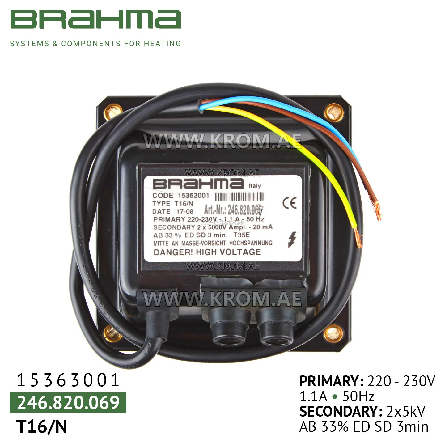
Brahma 15363001 T16/N ignition transformer
The ignition transformers BRAHMA T16/N 15363001 are suitable for burners with liquid or gaseous fuels. Features 1. Various connection and mounting systems: - An extensive variety of connection and mounting systems provides flexibility in integrating transformers into various types of equipment. - This allows users to choose the best connection and mounting options according to specific requirements and conditions of use. 2. High discharge power: - Ignition transformers BRAHMA T16/N 15363001 have high discharge power, which makes them an ideal choice for applications where long ignition wires are required. - This characteristic is especially useful in situations where it is necessary to ensure stable and efficient ignition over a considerable distance. 3. High ignition efficiency and power: - BRAHMA T16/N 15363001 high voltage transformers provide high ignition efficiency and power, making them suitable for various applications where efficient use of energy and reliable ignition are required. - These characteristics make transformers an ideal choice for situations requiring outstanding ignition characteristics. Such transformers represent a reliable and efficient solution for systems where high efficiency, discharge power and variety in connection and mounting systems are important. Technical data - Supply voltage: 220 V - 50 Hz - Operating temperature range: -10°C +35°C - Insulation: polyester resin - Recommended distance between electrodes: 3 - 5 mm - Standard length of the power cable: 700 mm - Number of poles: 2 - Output peak voltage (KV): 2 x 8 - Output effective voltage (KV): 2 x 5 - Output effective current (mA): 20 - Input effective current (A): 1.1 - Duty cycle: 33% in 3 minutes - Power consumption (VA): 240 - Weight (kg): 2 - Dust and moisture protection class: IP 00 - Ignition cable connectors: screw Ø2.5 mm - Dimensions: 11.5x8x7.8 cm Construction The magnetic circuit on the spark transformer BRAHMA T16/N 15363001 has the shape of a shell. The secondary windings are grounded in the center. The high-voltage transformer BRAHMA T16/N 15363001 is equipped with a radio interference suppression screen, which must be connected to a reliable ground to ensure its effectiveness. Two caps painted with flame retardant paint cover the coils and form a single unit with a magnetic circuit. Each transformer is identified by a fixed letter T (transformer), a series of numbers indicating the model, and possibly an alphabet letter that defines a specific mounting system. If the mounting system used is standard, the corresponding letter of recommendation is not inserted in the part reference. For example, the part designation T11 refers to a transformer with a standard mounting system, whereas the part designation T11/N corresponds to a transformer T11 with a different mounting system. Ignition devices BRAHMA T16/N 15363001 may have the same electrical characteristics, but different mounting systems, or vice versa. Connection The high-voltage insulators used in BRAHMA T16/N 15363001 transformers come in two different types, depending on how the connection to the high-voltage cables is made using a screw, a cylindrical terminal with a diameter of 4 mm or a cylindrical terminal with a diameter of 6.3 mm. Unless explicitly stated, a screw terminal is used as the connecting terminal. The insulators are made of 30% PBT fiberglass. Installation - Be careful! Dangerous voltage may be present. - Connect and disconnect the ignition transformer only after disconnecting the power supply. - Comply with applicable national and European standards (e.g. EN 60335-1 / EN 60335-2-102) regarding electrical safety. - Make sure that the transformer ground and the electrical system ground are well connected. - Place a single grounding center, thus preventing the formation of ring tracks from the grounding conductors. - The device can be installed in any position. - Reduce the length of the ignition cable to a minimum (this reduces parasitic capacitance and the likelihood that the ignition cable will act as an antenna transmitting interference to nearby cables). - Route the ignition cables along a separate path near the grounding planes (this reduces the effect of interference on the remaining electrical wires). - Avoid placing high voltage cables near other cables. - Make sure that the degree of protection corresponds to the system.