

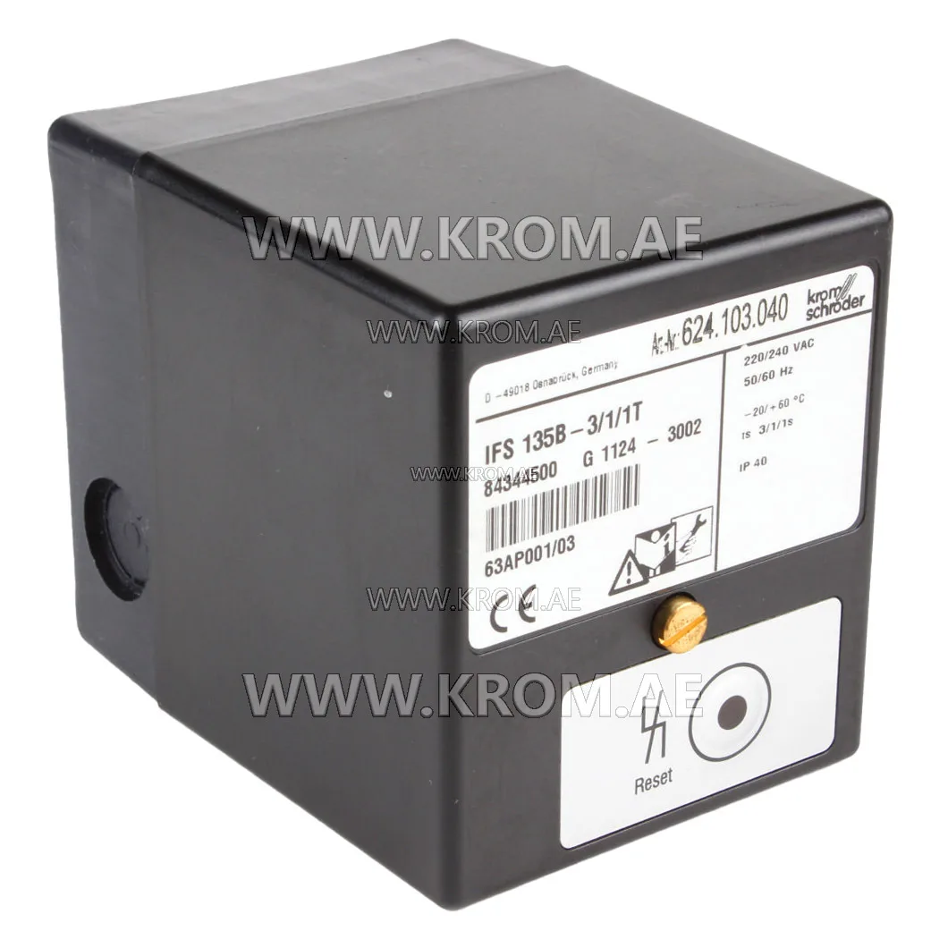
Moduł sterujący palnika Kromschroeder IFS135B-3/1/1T (84344500)
Kromschroder IFS135B-3/1/1T 84344500 automatic burner control units are suitable for the ignition and control of gas burners in gas firing installations of all types. Range of application according to EN 746-2. For the flame control by means of ionization probe or UV-cell. With ionization control, a grounded main is required. Kromschroeder IFS135B-3/1/1T 84344500 control boxes are EC type tested and certified pursuant to the Gas Appliances Directive (90/396/EEC) in conjunction with EN 298. Krom schroder 84344500 IFS135B-3/1/1T automatic gas firing device technical data Mains voltage: 220/240 V, 50/60 Hz Power consumption: Approx. 18 VA Output for ignition transformer via relay contact Output voltage for valves and ignition transformer = mains voltage Contact rating: Max. 1 A per output Total load: Max. 2 A Average number of operating cycles depending on power factor cos ϕ: Approx. 1,000,000 Reset button: Max. number of operating cycles: 1000 Signal input: Remote reset Flame control: Sensor voltage: 220 V AC Sensor current: > 1 µA Reaction time: < 1 s Valve connections: 2 Fuse in unit: F1: 2 A, semi time-lag E, pursuant to DIN 41571 V/EN 60127-1 Ambient temperature: -20 °C to +60 °C Climate: no condensation permitted Enclosure: IP 40 pursuant to IEC 529 Cable gland: PG 9 Installation position: Arbitrary Weight: 390 g Kromschroder IFS135B-3/1/1T 84344500 gas burner control box operation Upon receiving a heat call from the thermostat, the control initiates a sequence of checks. The control checks for flame simulation and activates failsafe measures during the testing period. If no flame signal is detected, the burner is started by applying voltage to valve V1 and the ignition transformer. If flame simulation is detected, the testing time is extended up to five seconds. After the testing period, if no flame signal is detected, the control goes into lockout mode. Following the burner start, a flame signal must be measured within the safety time. Upon ignition, voltage is applied to valve V2, causing it to open. If a flame fails to establish, the control enters fault lockout mode. During burner operation, the control continuously monitors for a flame signal. Fault lockout is indicated both internally and externally, with the fault indication retained during regulating stop. Resetting is possible even during regulating stop. Following a flame failure during operation, a reigniting attempt is made. However, valve V2 is switched off during this process. The flame must be detected within the safety time frame; otherwise, the control goes into fault lockout mode.